Olight sells some of the products discussed here through its OSelect store. Olight specs and prices come from its product pages as of September 2026; other brands' specs come from their makers; diagnostic reference values come from the trade and manufacturer sources linked in each section.
⚡ TL;DR
The best thermal imaging camera for mechanics, for most shops, is a 256 × 192 phone plug-in like the TC001 Max, sold through Olight's OSelect store. This guide compares four current cameras on their makers' published specs, not bench trials. The TC001 Max leads on native pixels per dollar and on close focus, which matters on fuses and exhaust runners. Pick a pistol-grip standalone if phones stay out of your bay.
This table sums up which camera fits which shop situation, with prices checked on September 24, 2026.
| Situation | Pick | Key spec (maker) | Price | Why |
|---|---|---|---|---|
| Best overall for general repair | TC001 Max (OSelect) | 256 × 192 IR, ≤40 mK NETD, 56° × 42° FOV, -4°F to 1,022°F | $309.00 (regular price, September 2026) | 49,152 native pixels, 0.66 ft minimum focus, plugs into iPhone, Android or Windows |
| No phone in the bay, hot exhaust work | FLIR TG298 | 160 × 120 IR, 57° × 44° FOV, up to 1976°F, IP 54 | $899.00 (FLIR) | Pistol grip, own battery, 2 m drop rating, emissivity adjustment |
| Wi-Fi standalone for electrical checks | Klein Tools TI270 | 10,800 pixels, ≤60 mK, -4° to 752°F | Not listed on Klein's page | Adjustable emissivity 0.01 to 0.99; lower ceiling for exhaust work |
| Lighting the bay and the fuse legend | Olight Warrior X 4 | 2,600 lumens, 99,310 candela, 300 lumens for 8 hours | $129.99 (regular price, September 2026) | A thermal image shows heat, not fuse numbers or cracked boots |
| Off-the-clock scanning outdoors, not shop work | TS004 monocular (OSelect) | 256 x 192 IR, 13.5° x 10.10° FOV, 410 m detection | $499.00 (regular price, September 2026) | Built for distance; too narrow and not a measuring tool for a fuse box |
A scan tool gives you a P0300 and a list of guesses. A customer's battery dies every two days, and pulling fuses one at a time eats an hour. A pull to the right could be a caliper, a hose or a tire. A thermal camera turns each of those into a comparison you can see in seconds. The sections below explain which comparisons are worth making, what temperature gaps published sources treat as meaningful, and where the picture stops being proof.
📋 Table of Contents
- 1. What Is the Best Thermal Imaging Camera for Mechanics?
- 2. Which Thermal Cameras Are Suitable for Automotive Diagnostics?
- 3. Three High-Payoff Uses: Misfires, Brake Drag and Parasitic Draw
- 4. How Long After a Cold Start Should You Scan the Exhaust Manifold?
- 5. How Do You Find a Dragging Brake With a Thermal Camera?
- 6. How to Find a Parasitic Draw With a Thermal Camera at the Fuse Box
- 7. Phone Plug-In vs Standalone Thermal Camera: Which Works Better in a Shop?
- 8. Common Mistake: Using a Heat Map Instead of an Ammeter Reading
- 9. How Should You Take Thermal Photos for Customers?
- 10. Who Makes the Best Thermal Imaging Camera?
- 11. What Are the Top 10 Thermal Imaging Cameras?
- 12. How This Guide Compared the Cameras
- 13. Which Thermal Camera Should a Mechanic Buy?
- 14. FAQ
What Is the Best Thermal Imaging Camera for Mechanics?
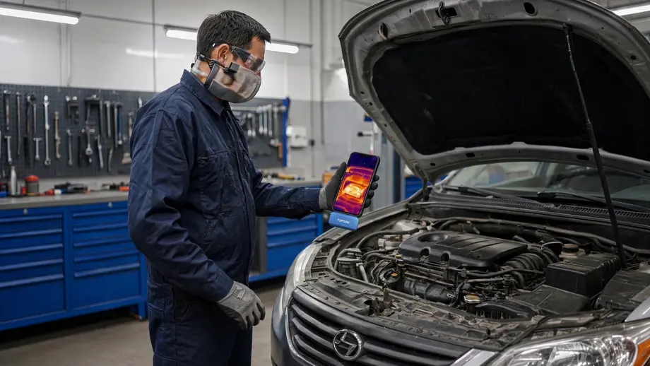
The best thermal imaging camera for mechanics is one that lets you compare similar parts in one frame: exhaust runners after a start, four brake rotors after a drive, or a row of fuses with the key off. For that job, a 256 × 192 sensor with a wide field of view, close focus and a visible-light overlay beats a costly camera with fewer pixels.
Think of the camera as a comparison tool, not a thermometer. Every use in this guide works by setting one part against its twin: cylinder 3 against cylinders 1, 2 and 4, left front rotor against right front, fuse 15 against the fuses beside it. The absolute number on the screen matters less than the gap between two similar surfaces in the same image.
That is also how trade trainers describe the method. Amprobe, a test-tool maker, says in its automotive thermal camera application note that ports of misfiring cylinders "will show lower temperature than others," and that a "significant temperature difference" between left and right front rotors "may indicate dragging or sticking calipers." Snap-on's Diagnostic Thermal Imager user manual gives the same misfire example: "The non-firing cylinder can be identified as a 'cold' exhaust runner compared to the others." Neither guide sets a degree threshold. Both read the gap between twins.
Three camera specs decide how well that comparison works in a shop:
- Native resolution. More sensor pixels put more measurement points on a small fuse or a single exhaust runner. Upscaled numbers (TOPDON's TISR turns 256 × 192 into 512 × 384) sharpen the picture but do not add measured pixels.
- Field of view and minimum focus. A wide view (56° × 42° on the TC001 Max thermal imager) fits a whole fuse box or both front wheels from close range. Close focus lets you fill the frame with a small part.
- Temperature ceiling. Olight lists the TC001 Max to 1,022°F (550°C). In a Hot Rod Q&A on exhaust temperatures, engine builder Ken Duttweiler quotes 900 to 1,000 degrees on the outside of a header tube at 3,000 rpm under load, so a ceiling near 1,000°F covers most engine bay work.
Which Thermal Cameras Are Suitable for Automotive Diagnostics?
Thermal cameras suitable for automotive diagnostics measure at least -4°F to about 1,000°F, have a field of view near 55° wide, focus within about a foot, and save both a thermal and a visible image. The TC001 Max and FLIR TG298 both meet that bar. The Klein TI270 stops at 752°F, and outdoor monoculars built for spotting animals at distance do not measure close parts at all.
This table lines up the four current cameras on their makers' published specs. It compares specs, not performance in a bay.
| Spec (maker) | TC001 Max (OSelect) | FLIR TG298 | Klein TI270 | TS004 monocular (OSelect) |
|---|---|---|---|---|
| Native IR resolution | 256 x 192 (49,152 pixels) | 160 × 120 (320 × 240 super resolution) | 10,800 pixels | 256 x 192 |
| Thermal sensitivity (NETD) | ≤40 mK | Under 50 mK | ≤60 mK | Under 40 mK |
| Field of view | 56° x 42° | 57° × 44° | 50° +/- 3° | 13.5° x 10.10° |
| Measurement range | -4°F to 1,022°F | -13°F to 1976°F | -4° to 752°F | Not listed as a measuring range |
| Accuracy | ±2°C or ±2% of reading, larger value | ±2.5% or 2.5°C (0 to 50°C and 100 to 400°C) | ±3°C or 3%, whichever is greater | Not listed |
| Frame rate | 25 Hz | 8.7 Hz | Under 9 Hz | 50Hz |
| Minimum focus | 0.66 ft (0.2 m) | 0.98 ft (0.3 m) | Not listed | Not listed |
| Weight | 30 g (0.06 lbs) | 13.9 oz | 7.5 oz | 330 g (0.728 lbs) |
| Protection rating | IP54, 1 m drop | IP 54, 2 m drop | Not listed | IP67, 2.0 m |
| Power | From the phone or PC | Rechargeable, 5 hours scanning | Rechargeable lithium-ion | 5000mAh, 11 hours |
| Price (September 2026) | $309.00 (regular price) | $899.00 | Not listed | $499.00 (regular price) |
Sources: Olight product pages for the TC001 Max and TS004; FLIR's TG298 page; Klein Tools' TI270 page.
You may also see the TOPDON TC002C Duo in other roundups. It is a 256 × 192 plug-in from the same maker as the TC001 Max, with the same 56° × 42° view and -4°F to 1,022°F range listed by TOPDON. Olight's store does not sell it, so this guide treats it as a spec reference only and does not rank it.
Two numbers in that table deserve a second look. The TS004's 13.5° × 10.10° field of view is about a quarter as wide as the others, because it is built to spot heat at distance. That makes it a poor fit for a fuse box two feet away. The TG298's 8.7 Hz frame rate is fine for still parts but slower when you pan along a running engine.
Price per measured pixel is a useful tiebreaker. Dividing each price by native pixels gives about $6.29 per 1,000 pixels for the TC001 Max and $46.82 for the TG298, a gap of more than seven to one. The FLIR costs more for things a phone camera can't give you: its own screen, battery and grip, and a range up to 1976°F.
Three High-Payoff Uses: Misfires, Brake Drag and Parasitic Draw
The three uses that repay a thermal camera fastest are finding a misfiring cylinder by its cooler exhaust runner, finding a dragging brake by its hotter rotor, and narrowing a parasitic draw to a warm fuse or module. Each one is a side-by-side comparison, and each points you to where the real test belongs.
ASE's task lists show where each job sits in a technician's workflow. The ASE Automobile Study Guide names "thermal imaging" readings for HVAC diagnosis in the A7 test. For parasitic draw, the A6 task is to "measure and diagnose" key-off battery drain. Brake drag appears under A5 disc brake diagnosis, and misfire under A8 ignition diagnosis. The camera speeds up those tasks; it does not replace the measurement each one calls for.
This table separates what tool and brake makers publish from the degree figures one technician uses. The maker column is the method; the technician column is a reference point, not a standard.
| Job | What to compare | What maker guides say | One technician's rule of thumb | Confirm with |
|---|---|---|---|---|
| Misfire | Exhaust runners near the head, same spot on each | A misfiring cylinder's runner or port reads cooler than the others (Snap-on, Amprobe) | Warm engine: runners within about 50°F are normal; one 100°F or more cooler is suspect | Misfire counters, then spark, fuel and compression tests on that cylinder |
| Brake drag | Rotor faces on the same axle, same spot, soon after parking | A significant left-right gap may mean a dragging or sticking caliper (Amprobe); Bendix's commercial-vehicle guide inspects any brake that differs by more than about 50°C (90°F) | 20 to 30°F side to side is normal; one rotor 100°F or more hotter is suspect | Wheel spin by hand, slide pins, hose and piston checks |
| Brake overheating | Any rotor or pad after hard use | 250°F to 300°F under normal conditions; 600°F to 700°F when overheating (Wagner) | No separate figure used | Pad and rotor inspection, driving history |
| Parasitic draw | Fuses and modules with the network asleep | Under 50 mA total draw is a good guide; an awake module can draw up to 150 mA (Snap-on) | Case study: an 800 mA draw traced through a warm fuse (Scott Shotton, AES) | Ammeter reading before and after each suspect is disconnected |
The maker guides agree on the method, but none of them publishes a degree threshold for passenger-car misfires or brake drag. The degree figures in the fourth column come from one ASE Master Technician, Anthony Calhoun, in his APEX Tech Nation guides on thermal misfire detection and brake and chassis thermal diagnostics. They reflect his field experience, not an industry standard. The brake maker Bendix makes the core point in its guide to IR temperature measurement on brakes: "it is not the absolute temperature we are interested in but the difference between brakes." The overheating range comes from brake maker Wagner's guide on how to know if your brakes are overheating. The draw limits come from Snap-on's technical article on parasitic draw diagnosis.
Without a published number, read each gap against the spread among the healthy parts. This relative method works on any engine or axle:
- Pick true twins. Same part type, same material, same load: the other runners on one bank, or the rotor across the same axle. Never front against rear.
- Read the same spot at the same distance. Use a spot or box readout on the same feature of each part.
- Measure the normal spread first. Take a worked example: if three runners on a four-cylinder read 520, 535 and 545°F, the healthy spread is 25°F.
- Look for a clear outlier. In that example, a fourth runner at 380°F sits 140°F below the coolest healthy one, more than five times the healthy spread. A runner at 510°F is only 10°F below it and is not a lead.
- Repeat the scan. A real fault shows the same outlier on a second frame a minute later.
- Confirm with a measurement. The gap tells you where to test, not what failed.
Note: Manifold design, heat shields, driving style and ambient temperature all move the numbers. Treat any degree figure in this guide as a reference, and when the vehicle maker publishes a spec or test procedure, follow it first.
How Long After a Cold Start Should You Scan the Exhaust Manifold?
No trade body publishes a set number of seconds for a cold-start misfire scan. One ASE Master Technician's published procedure, at APEX Tech Nation, warms the engine to full operating temperature, then compares runners. A cold start can give a quicker first look, because firing cylinders heat their runners while a dead one lags. Save frames at several points and confirm with misfire counters.
The two approaches answer different questions. The warm-engine method is the one Calhoun attaches numbers to. In his experience, runners within about 50°F are normal, and a runner 100°F or more cooler marks the misfiring cylinder. The guide calls warming the engine "not optional," because "a cold or partially warmed engine will show inconsistent runner temperatures."
The cold-start look is a screening shortcut, not a standard. If a cylinder does not fire at all, its runner starts heating later than its neighbors. That gap is easiest to see before heat spreads through the manifold. An intermittent or partial misfire may not show up this early, which is why the warm scan still matters.
This routine combines both into one visit. The time marks are a practical grid for this guide, not a published spec.
| Step | When | What to capture | What it tells you |
|---|---|---|---|
| 1 | Before start, engine cold | One frame of the manifold | A baseline so you know every runner started even |
| 2 | About 30 seconds after start | Same angle, same distance | Which runners are heating first |
| 3 | About 60 seconds | Same angle | Whether a lagging runner is catching up |
| 4 | About 120 seconds | Same angle | Whether heat soak has blurred the difference |
| 5 | Full operating temperature | Spot readings at the same point on each runner | The comparison the technician's reference figures assume |
| 6 | After the scan | Misfire counter data from the scan tool | A second, independent pointer to the same cylinder |
Manifold design decides how well this works. The APEX guide notes that log-style manifolds, where runners merge close to the head, "make it difficult to isolate individual cylinder temperatures," while tubular headers are ideal. Heat shields and exhaust leaks also distort readings. On a V engine, compare runners within one bank before you compare banks.
Safety note: A running engine has spinning belts, pulleys and fans, and Amprobe lists those moving parts among the hazards a non-contact camera helps you avoid touching. Set the parking brake, put the transmission in Park or neutral as the maker directs, and keep the camera's cable, your sleeves and the phone clear of the belt path. Treat an electric cooling fan as able to start at any time.
How Do You Find a Dragging Brake With a Thermal Camera?
To find a dragging brake with a thermal camera, drive 5 to 10 minutes with several moderate stops, park, and scan all four rotors within two minutes. Compare left to right on each axle, not front to rear. A rotor clearly hotter than its partner points to a caliper that is still applying. One ASE Master Technician treats 20 to 30°F as normal spread and 100°F or more as a fault.
Front rotors normally run hotter than rears, because fronts do most of the braking. The APEX brake guide puts the front share at 60 to 70 percent on most vehicles. Comparing a front rotor with a rear one is the most common way to misread a brake scan.
The same guide suggests a test drive at 25 to 45 mph with at least three to five moderate stops from 30 mph or higher. A slow lap of the parking lot does not load the brakes enough. The sooner you scan after stopping, the bigger the gap between corners, since rotors lose much of their heat within about 10 minutes.
A hot corner and a cold corner mean different things:
- One rotor much hotter than its partner: the caliper is still applying. The APEX guide lists seized slide pins, a collapsed hose acting as a one-way valve and a seized piston as the common causes.
- One rotor much cooler than its partner: that corner is not doing its share. Contaminated pads, air in the caliper or a restricted hose are typical causes.
- Both fronts hot and both rears cool: the rear brakes may not be working as they should. Look at rear hydraulics and, on newer cars, brake force distribution.
- A hot hub rather than a hot rotor: consider the wheel bearing. APEX reports a severely worn bearing may run 80 to 100 degrees hotter than healthy ones after highway driving.
Aim at the same spot on each rotor. The friction face of a rotor is machined cast iron, and Fluke's emissivity chart for common materials lists polished cast iron at 0.21, against 0.81 for a rough casting. A shiny face can read far below its true temperature and reflect nearby heat. The rotor hat or the rough outer edge often gives a steadier comparison.
Warning: Brakes that read 250°F to 300°F after normal driving, the range Wagner gives, will burn skin instantly. Never touch a rotor, caliper or wheel to "check" a thermal reading, and chock the wheels before you lean in to scan a car on the ground.
How to Find a Parasitic Draw With a Thermal Camera at the Fuse Box
To find a parasitic draw with a thermal camera, measure the draw with an ammeter first, let the vehicle's network go to sleep, then scan the fuse boxes for a fuse warmer than its neighbors. Follow that fuse on the wiring diagram to the modules it feeds, scan those, and confirm by watching the ammeter drop when you disconnect the suspect.
A case study by technician Scott Shotton, published by AES, shows the method working. In his write-up on thermal imaging and parasitic draw, a 2007 Honda Odyssey had about an 800 mA draw, confirmed with a Fluke ammeter. Removing aftermarket boxes cut it to 430 mA. A thermal image then showed fuse #15 warm, the wiring diagram led to fuse #7, and the scan found the right power sliding door module "glowing brightly." Disconnecting it brought the draw to 20 mA.
Shotton explains why he looks before he pulls: "I do not like to remove fuses unless I have to because I do not want to accidentally wake up a module." The camera lets you narrow suspect circuits without disturbing anything.
Follow these steps in order:
- Measure first. Connect an ammeter in series at the battery and record the draw. Snap-on calls less than 50 mA "a good guide" for a sleeping vehicle.
- Let the network sleep. Snap-on says a vehicle normally shuts down fully within 10 minutes, and some wake again after a few minutes. Move keyless-entry fobs away from the vehicle and unplug the scan tool, since pin 16 of the data link connector stays live.
- Scan without touching. Open the fuse box covers early, then wait. Shotton found that a plastic panel still showed his hand's heat 3 minutes after a 15-second touch.
- Compare fuses of the same rating side by side. A warm fuse is a lead, not a verdict.
- Follow the circuit. Use the power distribution diagram to find the modules downstream of the warm fuse, and scan them.
- Confirm with the meter. Disconnect the suspect and watch the draw fall.
Small draws make small heat. The power a fuse turns into heat rises with the square of the current, so this table shows how much less heat each draw makes compared with a 1 A load through the same fuse.
| Draw | Share of the heat at 1 A | Where the number comes from |
|---|---|---|
| 1 A (1,000 mA) | 100% | Reference load |
| 800 mA | 64% | Shotton's starting draw |
| 430 mA | About 18% | Shotton's draw after removing aftermarket parts |
| 150 mA | About 2% | Snap-on's example of a module left powered |
| 50 mA | 0.25% | Snap-on's guide for a healthy sleeping vehicle |
| 20 mA | 0.04% | Shotton's final draw after the repair |
The practical takeaway: a draw of several hundred milliamps usually leaves a trail you can see, as in Shotton's case. A draw near 50 mA puts very little heat into a fuse, so an even-looking fuse box does not clear a circuit. Snap-on's article shows the other place to look. A module that stays awake heats its own casing, and the image showed "localized heating around the Microprocessor."
Phone Plug-In vs Standalone Thermal Camera: Which Works Better in a Shop?
A phone plug-in thermal camera gives you more sensor pixels per dollar, a large screen and instant photo sharing. A standalone camera gives you a trigger grip, its own battery and a sealed body built for drops and oil. Choose a plug-in if you already carry a sturdy phone, and a standalone if you work under cars all day or share one tool across bays.
This table compares the two formats using the TC001 Max and the FLIR TG298 as examples.
| Factor | Phone plug-in (TC001 Max) | Standalone (FLIR TG298) |
|---|---|---|
| Native pixels | 49,152 | 19,200 |
| Power | From the phone; "no batteries, charging, or wireless pairing required" | Built-in battery, 5 hours continuous scanning |
| Screen | Your phone's screen | 2.4 in, 320 × 240 |
| Handling | Two hands, phone plus camera; case-friendly connection | One hand, pistol grip, wrist strap |
| Protection | IP54, 1 m drop | IP 54, designed for a 2 m drop |
| Operating temperature | 14°F to 122°F | 14°F to 113°F |
| Sharing with customers | Photos and video already on the phone | Transfer by USB or Bluetooth |
| Price | $309.00 | $899.00 |
Watch the operating temperature on either format. The TC001 Max is rated for 14°F to 122°F and the TG298 for 14°F to 113°F, both far below the temperature of an exhaust manifold. Scan from a distance, and never set the camera or the phone down on a valve cover, radiator or fender over a hot engine.
A shop note on phones: a phone in the engine bay is a phone that can fall into the engine bay. Olight's page says the TC001 Max connects through USB-C or a Lightning adapter without removing most cases. A lanyard on the phone case is cheap insurance.
Common Mistake: Using a Heat Map Instead of an Ammeter Reading
The most common thermal camera mistake in automotive work is treating the picture as the measurement. A heat map shows where to look; the ammeter, scan tool, compression gauge or micrometer tells you what is wrong. Shiny surfaces, parts too small for the sensor and leftover heat from your hands all produce convincing images that are wrong.
These mistakes come up most often, each with its fix:
- Reading a warm fuse as the answer. Fix: note the draw on the ammeter before and after you disconnect the suspect. ASE's A6 task says "measure," and a thermal image is not a current reading.
- Trusting absolute temperatures on bare metal. Fix: compare the same material at the same angle, or put a strip of black electrical tape on the spot. Fluke lists black plastic tape at 0.95 emissivity.
- Measuring a target that is too small. Fix: move closer until the part covers many pixels. A peer-reviewed study in Sensors on the size-of-source effect in thermal imaging found that small targets read "too low" and recommends at least 10 × 10 pixels on the target, using the central 3 × 3 for the value.
- Scanning right after you handled the part. Fix: wait a few minutes, as Shotton's 3-minute handprint shows.
- Stopping at the cylinder. Fix: the APEX guide stresses that thermal detection "identifies which cylinder is the problem. It does not tell you why."
This table uses Fluke's published emissivity values for surfaces you meet under the hood.
| Surface | Emissivity (Fluke chart) | What it means for your reading |
|---|---|---|
| Cast iron, rough casting (manifolds, rotor edges) | 0.81 | Usable for comparisons |
| Cast iron, polished (fresh rotor face) | 0.21 | Reads low and reflects nearby heat |
| Steel, oxidized strongly | 0.88 | Usable |
| Steel, rusty red | 0.69 | Fair; compare rust to rust |
| Aluminum, polished | 0.05 | Mostly reflection; do not trust the number |
| Aluminum, strongly oxidized | 0.25 | Still unreliable |
| Rubber (hoses, boots) | 0.93 | Good target |
| Electrical tape, black plastic | 0.95 | Add a strip to create a reliable spot |
Resolution sets how close you need to be. With a 56° view across 256 pixels, each TC001 Max pixel covers about 3.8 mm at 1 m (about 0.15 in at 3.3 ft). To put 10 pixels across a 10 mm (0.39 in) part, you need to be within about 262 mm (10.3 in), which the 0.66 ft minimum focus allows. The TG298's 160 pixels over 57° need about 161 mm (6.3 in) for the same coverage. That is closer than its 0.98 ft minimum focus, so small parts get only a few pixels each.
How Should You Take Thermal Photos for Customers?
Take thermal photos for customers as a matched pair: one thermal image and one visible-light image of the same part from the same angle. Include the good side in the frame for comparison, turn on a spot or area readout, and save the before and after images. A customer understands "this rotor is 120 degrees hotter than that one" faster than a paragraph of explanation.
FLIR pitched the ability to "save images to show the customer and demonstrate the problem" in its own guide to thermal cameras for mechanics. That article featured the TG275, which FLIR now lists as discontinued, with the TG298 as its suggested replacement. Check that any camera you read about is still sold before you plan around it.
This shot list works for most repair orders:
- Wide shot with context. Show the whole axle, fuse box or manifold so the customer knows where they are looking.
- Close shot with the reference in frame. Left and right rotor, or the suspect runner next to a healthy one.
- Numbers on screen. Use spot or area readings. The TC001 Max lists center, hot and cold spots, plus up to 3 user-set points, lines and rectangles.
- One palette for the whole job. Iron red or white hot, and keep it the same for before and after.
- A visible-light twin. The TC001 Max's dual-lens fusion helps here, and a plain photo of the part with its label or fuse number helps more.
- The after image. Same angle, same palette, after the repair.
Good light makes step 5 easy. The Olight Warrior X 4 tactical flashlight puts out up to 2,600 lumens and 99,310 candela, with a 300 lumen low mode Olight rates at 8 hours. That low mode suits reading a fuse legend or checking a caliper boot. It has a tail switch, an IPX8 rating and USB-C or magnetic charging.
The limits: it is a large tactical light, 8.78 oz (249 g) with its battery, and it is not hands-free. For hours under a hood, a headlamp or magnetic work light fits better, and Olight's guide to mechanic flashlights and automotive work lights covers those options. Also keep a warm light head out of the reflection on shiny parts when you take the thermal shot.
Who Makes the Best Thermal Imaging Camera?
No single company makes the best thermal imaging camera for every job. FLIR (Teledyne FLIR) builds handheld cameras across price ranges and made a model aimed at automotive technicians. Fluke and Klein Tools build cameras for trades. TOPDON makes phone plug-in cameras and automotive tools. The best maker for you is the one whose current model fits your work.
For a repair shop, sort makers by the format you want, then compare current models on the specs in the tables above. Four checks matter more than the brand name on the case:
- Is the model still sold and supported? The TG275 was built for automotive work and is now discontinued, per FLIR's product page.
- Does the maker publish a full spec sheet? Resolution, NETD, field of view, range and accuracy should all be listed. Klein's TI270 page, for example, lists no minimum focus distance.
- Can you adjust emissivity? FLIR lists adjustment from 0.1 to 0.99 on the TG298 and Klein lists 0.01 to 0.99 on the TI270.
- Does the software save radiometric data or just pictures? You want spot readings on saved images for repair orders.
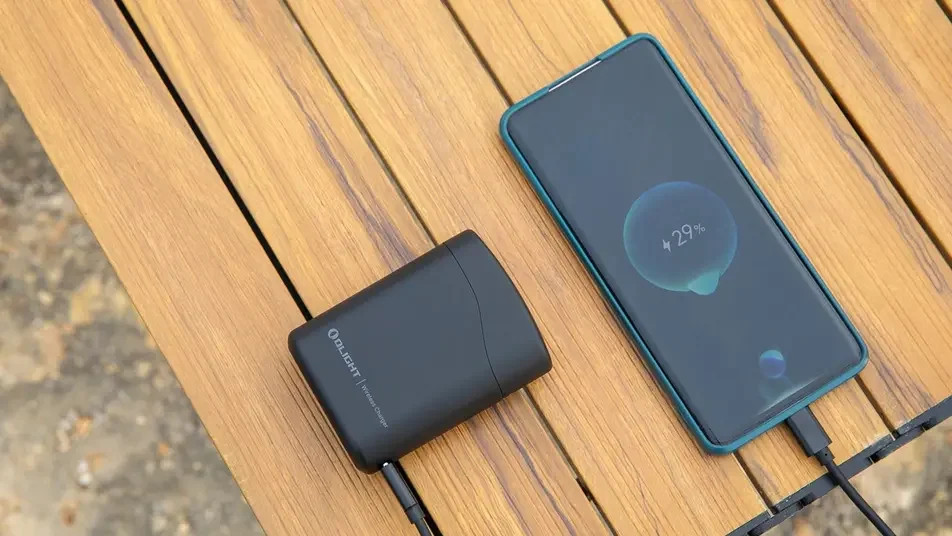
The TC001 Max sold through Olight is a TOPDON camera; its page describes it as "The TOPDON thermal camera." Olight's OSelect store carries it with other outside-brand gear, and Olight explains the program in what OSelect is.
What Are the Top 10 Thermal Imaging Cameras?
There is no neutral, published top 10 list of thermal imaging cameras for automotive work, and rankings change as models are discontinued. A better approach is a shortlist by format. For shops, that means a 256 × 192 phone plug-in, a pistol-grip standalone and a budget electrical imager. Four current models are compared in this guide.
This shortlist puts the four models in order of fit for general repair work, with the reason and the main limit for each.
| Rank for shop use | Model | Format | Best at | Main limit |
|---|---|---|---|---|
| 1 | TC001 Max | Phone plug-in | Pixels per dollar, close focus, customer photos | Depends on your phone; IP54 and 1 m drop |
| 2 | FLIR TG298 | Pistol grip | Hot exhaust, rugged use, no phone needed | 19,200 native pixels at $899.00 |
| 3 | Klein TI270 | Handheld | Wi-Fi transfer, emissivity adjustment | 752°F ceiling, 10,800 pixels |
| 4 | TS004 | Outdoor monocular | Seeing heat at distance | 13.5° field of view; not a measuring tool for close parts |
The TS004 thermal imaging monocular is on the list to show a mismatch. Olight's page lists a detection range of 410 meters and says it "penetrates fog and dense vegetation" for observing wildlife. Those strengths do nothing for a fuse box. For HVAC-specific picks, such as condenser coils and line sets, see the companion guide to the best thermal imaging camera for HVAC.
How This Guide Compared the Cameras
This guide compared cameras by collecting official specs and published diagnostic procedures, not by running shop trials. Specs come from each maker's product page on September 24, 2026. Reading methods come from tool and brake makers' guides. The degree figures for misfires and brake drag come from one ASE Master Technician and are labeled as his rules of thumb. Every calculation uses those published numbers.
This table sets out the method in detail.
| Item | Source | How it was used | Count |
|---|---|---|---|
| Camera specs and prices | Maker product pages (Olight, FLIR, Klein) | Copied as published; blanks marked "Not listed" | 4 current models, 1 discontinued, 1 spec reference |
| Reading method | Snap-on and Amprobe application guides, Bendix brake guide | Relative, twin-to-twin comparison | 4 jobs |
| Reference figures | Wagner, Snap-on, one ASE Master Technician (APEX Tech Nation), Hot Rod | Collected into the reference table, each labeled by source | 4 jobs |
| Task context | ASE Automobile Study Guide | Mapped each job to its ASE test area | A5, A6, A7, A8 |
| Surface emissivity | Fluke emissivity chart | Emissivity table for under-hood surfaces | 8 surfaces |
| Target size guidance | Peer-reviewed size-of-source study | Pixel footprint and distance calculations | 2 cameras |
| Current and heat | Square-law relationship of heat to current | Relative heat table for common draws | 6 draw levels |
Which Thermal Camera Should a Mechanic Buy?
Most mechanics should buy the TC001 Max if they already work with a sturdy phone, because it puts 49,152 native pixels, a 1,022°F ceiling and close focus into a $309.00 tool. Choose the FLIR TG298 if you want a sealed pistol grip and high-temperature range. Skip outdoor monoculars for shop work.
Use this checklist before you buy and on your first week with the camera:
- Check that the camera measures to at least 1,000°F and has a field of view near 55° wide.
- Confirm your phone's port (USB-C or Lightning) for a plug-in model, and add a lanyard.
- Keep an ammeter, scan tool and wiring diagrams as the final word on every thermal lead.
- Scan brakes within two minutes of parking, and compare left to right only.
- For misfires, save frames through warm-up and confirm with misfire counters.
- Put a strip of black tape on shiny metal when you need a real number.
- Keep the camera, phone and cable away from belts, fans and hot manifolds.
- Save a thermal and a visible photo of every finding for the repair order.
FAQ
Changelog
- September 21, 2026: First published. Olight and other makers' specs and prices checked September 24, 2026.