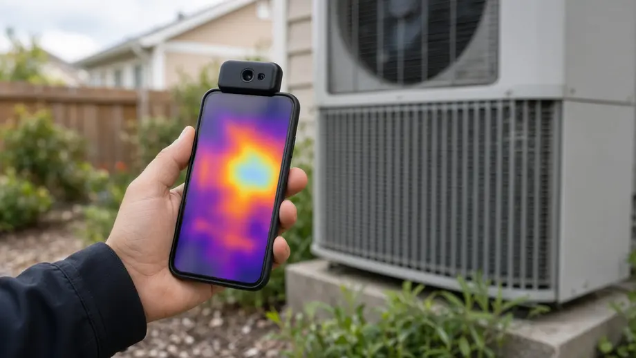
Olight sells the TC001 Max and TS004 through its OSelect store; both are TOPDON products. Olight specs and prices come from its product pages as of September 2026; other specs come from their makers. The cameras were compared on published specs, not in field trials.
⚡ TL;DR
The best thermal imaging camera for HVAC work, for most technicians, is a radiometric phone imager such as the TC001 Max. It reads -4°F to 1,022°F at ±2°C, shows a whole coil or floor in one frame, and connects to both Lightning and USB-C phones. Use it to find where to look, then confirm exact temperatures with a contact probe.
This table picks the best thermal imaging camera for HVAC jobs by task, using official specs and regular prices as of September 2026.
| Scenario | Recommended tool | Key spec (official) | Price | One-line reason |
|---|---|---|---|---|
| Overall pick for service techs | TC001 Max | 256 x 192 IR, -4°F to 1,022°F, IP54 | $309.00 (regular price, September 2026) | Radiometric, pocket size, Lightning and USB-C cables in the box |
| Radiant floor loops and homeowner checks | TC001 Max | 56° x 42° FOV, 0.66 ft minimum focus | $309.00 (regular price, September 2026) | About 20 sq ft of floor per frame from 5 ft up |
| Superheat and subcooling numbers | Pipe clamp or contact probe | Accuracy depends on the probe | Varies | A camera's ±3.6°F error is too wide for charging math |
| Supply and return air split | Air probe in the airstream | Accuracy depends on the probe | Varies | Cameras and IR guns read surfaces, not air |
| Outdoor scanning at distance | TS004 monocular | 13.5° x 10.10° FOV, IP67 | $499.00 (regular price, September 2026) | Built for outdoor viewing; no measurement range listed, so skip it for HVAC |
The usual frustration goes like this. Your infrared gun says the suction line is fine, the customer says the back bedroom is hot, and you have no way to show them what you mean. A spot reading covers one point. Frost on part of a coil, a radiant loop that never warms, or a duct boot leaking attic air all hide between the points you happened to check. The sections below cover which camera to carry, how to aim it at coils, line sets and floors, which temperature differences matter, and how to put it all in a report a homeowner will believe. Olight carries its OSelect thermal imaging cameras alongside its lights, and the picks below come from that lineup plus one TOPDON model sold directly by its maker.
📋 Table of Contents
- 1. What Is the Best Thermal Imaging Camera for HVAC?
- 2. Thermal Camera vs Infrared Thermometer vs Contact Probe: Which Tool Does What?
- 3. How Do You Scan an Evaporator Coil, Line Set and Supply Registers?
- 4. What Emissivity Should You Set for Copper Line Sets and Coils?
- 5. How Close Do You Need to Be to Read a Line Set?
- 6. How Do You Find Radiant Floor Heating Pipes With a Thermal Camera?
- 7. What Temperature Differences Should Worry You?
- 8. Can You Use Your Phone as a Thermal Camera for HVAC Work?
- 9. How Do You Make a Thermal Report Customers Trust?
- 10. What Is the Best Inspection Camera for HVAC Systems?
- 11. What Is the Best Thermal Camera for Homeowners?
- 12. Which Company Manufactures the Best Thermal Imaging Cameras?
- 13. How Should You Run a Thermal Check on Every Service Call?
- 14. FAQ
What Is the Best Thermal Imaging Camera for HVAC?
The best thermal imaging camera for HVAC measures temperature instead of only showing a picture, covers everything from frosted coils to hot connections, and fits in a tool pouch. The TC001 Max meets all three at $309.00 (regular price, September 2026): 256 x 192 infrared pixels, a -4°F to 1,022°F range, ±2°C accuracy and a 30 g body that plugs into your phone.
Measurement capability is the dividing line. The Department of Energy's O&M Best Practices Guide from Pacific Northwest National Laboratory separates two kinds of camera. A simple imager shows a thermal picture but "does not have the capability to analyze and quantify specific temperature values." A radiometric camera reports a temperature for any point you choose. For coils, line sets and breakers you want the radiometric kind.
This table compares the three OSelect and TOPDON thermal devices on their official specs.
| Spec (official) | TC001 Max | TC002C Duo | TS004 monocular |
|---|---|---|---|
| Infrared resolution | 256 x 192 (49,152 pixels) | 256 x 192 | 256 x 192 |
| Enhanced image | 512 x 384 via TISR | 512 x 384 via TISR | Not listed |
| Thermal sensitivity (NETD) | ≤40mK | Under 40 mK | Under 40 mK |
| Frame rate | 25 Hz | 25 Hz | 50 Hz |
| Field of view | 56° x 42° | 56° x 42° | 13.5° x 10.10° |
| Temperature range | -4°F to 1,022°F (-20 to 550°C) | -4°F to 1,022°F (-20 to 550°C) | No measurement range listed |
| Accuracy | ±2°C or ±2% of reading, whichever is larger | ±2°C or ±2% | Not listed |
| Close-range spec | 0.66 ft (0.2 m) minimum focus | 0.2 to 5 m temperature measurement distance | Not listed |
| Connection | iOS, Android and Windows; USB-C and Lightning cables included | Sold for iOS and Android USB-C devices, plus Windows | Standalone, 0.32 inch OLED |
| Ingress rating | IP54 | Listed as NA | IP67 |
| Weight | 30 g | 30 g | 330 g |
| Price, September 2026 | $309.00 (Olight) | $299.00 (TOPDON) | $499.00 regular price (Olight) |
The TC001 Max and TC002C Duo share the same sensor numbers, so the choice comes down to connection and protection. The TC001 Max thermal imager ships with a USB-C to Lightning cable and a USB-C extension, and Olight lists an IP54 rating. TOPDON sells the TC002C Duo as a model for "iOS & Android USB-C Devices" and lists its IP rating as NA. If anyone on your crew still carries a Lightning iPhone, or you want a stated dust and splash rating, the TC001 Max is the safer pick.
Keep the 512 x 384 figure in context. Olight's page says TOPDON's TISR technology "enhances thermal resolution from 256×192 to 512×384." The sensor still has 256 x 192 real pixels, and the pixel math later in this guide uses those real pixels.
Note: The TS004 thermal monocular is the wrong tool for HVAC. Its spec sheet lists "Professional Function: Outdoor," a narrow 13.5° field of view built for distance, and no temperature measurement range. Buy it for property walks or wildlife, not for coils.
Thermal Camera vs Infrared Thermometer vs Contact Probe: Which Tool Does What?
A thermal camera finds the problem, an infrared thermometer spot-checks a surface, and a contact probe gives the number you write on the ticket. None replaces the others. Cameras show patterns across thousands of points at once; IR guns average one circle; probes touch the pipe or sit in the airstream, so emissivity and reflections do not affect them.
The Kalos team puts it plainly in HVAC School's guide to the many uses of thermal imaging cameras in HVAC: "Thermal imagers are much better for qualitative comparisons." The same article says a thermal camera "isn't the most reliable tool for quantitative measurements." That is the right mindset. Use the image to decide where to clamp your probe.
This table splits the three tools by job, using official specs where they exist.
| Question | Thermal camera (TC001 Max) | IR thermometer (Fluke 62 MAX) | Contact probe or pipe clamp |
|---|---|---|---|
| What it reads | 49,152 surface points per frame | One averaged surface spot | The surface it touches, or air around the tip |
| Spot size | One pixel covers about 0.135 in at 3 ft | 10:1, so a 3.6 in circle at 3 ft | Tip size |
| Listed accuracy | ±2°C or ±2% | ±1.5°C or ±1.5% | See the probe's data sheet |
| Emissivity sensitive | Yes | Yes (0.10 to 1.00 setting range) | No |
| Best HVAC use | Frosted coil sections, restrictions, radiant loops, hot lugs, leaky boots | Quick surface checks on painted or taped spots | Superheat, subcooling, supply and return air split |
| Main weakness | Reads reflections off bare copper and foil | Spot is often wider than the pipe | One point at a time |
The spot size row is where most IR gun readings go wrong. The Fluke 62 MAX lists a 10:1 optical resolution, so at 3 feet it averages a 3.6 inch circle. A 3/4 inch suction line fills only a small part of that circle, and the rest is the wall behind it. To shrink the spot to 0.75 inch, you would have to hold the gun about 7.5 inches away.
How Do You Scan an Evaporator Coil, Line Set and Supply Registers?
Scan after the system has run 15 to 20 minutes, stand square to the surface, and look for breaks in a pattern rather than single numbers. A healthy evaporator coil cools evenly across its face; a line set shows steady color along its length; each supply register looks like its neighbors. Mark any odd spot, then confirm it with a probe.
HVAC School's guidance on furnace air temperature rise calls for letting the appliance "run for at least 15 to 20 minutes so that everything has a chance to acclimate." Use the same warm-up before thermal scans in heating or cooling, so the pattern you see is steady-state, not start-up.
Evaporator coil
- Look at the coil face through an access panel or filter slot with the blower running. A section much colder or warmer than the rest, or frost in patches, is worth a closer look. HVAC School notes that a full thermal picture can reveal restrictions within the coils and feeding issues.
- Use the Dual Fusion mode so the visible outline of the coil sits on the thermal image. It helps when you show the customer where the problem is.
- Aim at painted end sheets or taped tube bends for numbers. Bare aluminum fins reflect the room, so read them as a pattern only.
- Check the entering and leaving air with a probe, not the camera. HVAC School's where to measure delta T guide is blunt: "Don't use an infrared thermometer." A camera reads surfaces, and air has none.
Line set and condenser
- Follow the liquid line from the condenser outlet to the metering device. HVAC School notes that you "can see where a bright glow fades to a dimmer color," a sign of a restriction. The article pairs this with temperature clamps across filter-driers to decide whether one is clogged.
- Scan the condenser coil top to bottom. The same article explains that you can see the desuperheating, condensing and subcooling sections, and that "seeing too much subcooled liquid" can point to a restriction or overcharge when pressures agree.
- Put a strip of black electrical tape on bare copper before you take a number (see the emissivity section below).
- Clamp a probe at the same spot for superheat or subcooling. The camera's ±2°C is ±3.6°F for anything under 212°F, and that error swings charging math by several degrees.
Supply registers and duct boots
- Compare every register on one system in one pass, from the same distance and angle. A register that looks warmer than its neighbors in cooling mode may have a disconnected or crushed run.
- Look at the ceiling around each boot. Kalos techs look for "fuzzy plumes of hot or cold around the vent," a sign attic air is leaking in around the boot.
- Record the room temperature and outdoor temperature with each image. Patterns are easier to read on hot or cold days, when temperature swings are large.
Tip: If a nearby water heater or a sunny window shows up in a reflection, block it. Kalos notes that "a trash bag is a surprisingly effective way to block the heat emitted by other nearby objects."
What Emissivity Should You Set for Copper Line Sets and Coils?
Do not trust any emissivity setting on bare, shiny copper. Polished copper has an emissivity near 0.05, so the camera mostly sees reflected heat from you and the room. Put black electrical tape on the pipe, set the camera to the tape's emissivity, about 0.95, and read the taped spot. Oxidized copper, around 0.65, is better but still only a rough guide.
Emissivity is how well a surface gives off its own heat. Teledyne FLIR's explainer on how emissivity affects thermal imaging says "Highly polished metallic surfaces such as copper or aluminum usually have an emissivity below 0.10" and warns that "if the emissivity of the target you are trying to measure is below 0.5, you are unlikely to be able to get an accurate temperature measurement."
FLIR's radiant floor case study shows how big the error gets. On a heating manifold, a spot covered with electrical tape read the true fluid temperature of 44°C, while an untaped spot at nearly the same temperature read 30.5°C. That is a 13.5°C (24.3°F) error from emissivity alone. See the example in FLIR's floor heating inspection article.
This table lists emissivity values for surfaces you meet on HVAC calls, from the ThermoWorks emissivity table unless noted, with what to do about each.
| Surface on the job | Emissivity | Trust the number? | What to do |
|---|---|---|---|
| Polished copper line set | 0.05 | No | Tape it, or read pattern only |
| Oxidized copper | 0.65 | Rough guide | Tape it for any number you record |
| Polished aluminum (fins, foil tape) | 0.05 | No | Read the coil as a pattern |
| Anodized aluminum | 0.77 | Fair | Confirm with a probe |
| Galvanized steel duct or cabinet | 0.28 | No | Tape or read the painted parts |
| Black electrical tape | 0.97 (0.95 per Reclamation) | Yes | Your reference patch |
| Rubber (such as rubber pipe insulation) | 0.95 | Yes, for the insulation surface | Good for finding wet or missing insulation |
| Flat paint | About 0.90 (FLIR) | Yes | Walls, ceilings, painted cabinets |
| Concrete, rough | 0.92 to 0.97 | Yes | Radiant slabs |
| Glazed tile | 0.94 | Yes, if you avoid reflections | Radiant floors in baths and kitchens |
| Planed wood | 0.90 | Yes | Hardwood over radiant |
| Plaster | 0.86 to 0.90 | Yes | Ceiling boots and walls |
The U.S. Bureau of Reclamation's thermal analysis manual (FIST 4-13) gives the tape method in detail: black electrical tape (3M Scotch 33) has an emissivity of 0.95, and a 1/2 to 1 inch square should go on before the equipment is energized, loaded or heated. The manual adds that the target must run at least 20°F above ambient for the method to work. On a running system, give the tape time to reach the pipe temperature before you read it.
Warning: Shiny surfaces also reflect you. The FLIR explainer notes that "An object could be cool to the touch but show a much higher temperature according to your camera if a nearby heat source (such as the thermographer) was reflecting off the surface." Step a little to one side of square and see if the hot spot moves. If it moves with you, it is a reflection.
How Close Do You Need to Be to Read a Line Set?
Get within about 5 feet of a 3/4 inch suction line and within about 2 feet of a 3/8 inch liquid line with a 256 x 192 camera like the TC001 Max. At those distances the pipe spans three or more pixels, so the reading comes from the copper, not the wall behind it. Farther back, the pipe blends into the background.
The math uses Olight's published optics for the TC001 Max: 12 μm pixel pitch and a 3.2 mm lens. Pixel pitch divided by focal length gives each pixel's angular size, about 3.75 milliradians, which matches the 56° field of view spread over 256 pixels. At 1 foot, one pixel covers about 0.045 inch of surface.
The Bureau of Reclamation manual says "The thermographer needs to recognize the spot size and ensure that the target size is adequate and is in focus." This guide uses three pixels across the target as a working minimum, so at least one pixel sits fully on the pipe. This table shows how many pixels land across common line sizes at each distance.
| Distance | Surface per pixel | 3/8 in liquid line | 3/4 in suction line | 7/8 in suction line | Fluke 62 MAX spot (10:1) |
|---|---|---|---|---|---|
| 1 ft | 0.045 in | 8.3 pixels | 16.7 pixels | 19.4 pixels | 1.2 in |
| 2 ft | 0.090 in | 4.2 pixels | 8.3 pixels | 9.7 pixels | 2.4 in |
| 3 ft | 0.135 in | 2.8 pixels | 5.6 pixels | 6.5 pixels | 3.6 in |
| 5 ft | 0.225 in | 1.7 pixels | 3.3 pixels | 3.9 pixels | 6.0 in |
| 10 ft | 0.450 in | 0.8 pixels | 1.7 pixels | 1.9 pixels | 12.0 in |
Two practical results come out of this. First, a phone camera is fine for a line set if you walk up to it; the TC001 Max focuses as close as 0.66 feet. Second, an IR gun never gets its spot onto a 3/8 inch liquid line at a normal working distance, which explains many "the line looks fine" readings.
The same numbers set how much you see per frame. At 3 feet the TC001 Max's 56° x 42° view covers about 38 x 28 inches, enough for a typical indoor coil face. At 5 feet it covers about 5.3 x 3.8 feet, or roughly 20 square feet of floor.
How Do You Find Radiant Floor Heating Pipes With a Thermal Camera?
Scan a radiant floor while it warms up, not after it has been running for hours. Start from a cool slab, call for heat, and scan every 10 to 15 minutes from standing height. Tubing appears first as warm stripes over each loop; once the slab evens out, the stripes fade. Mark loop paths with tape before anyone drills or nails.
Timing matters because heat spreads sideways through the slab or screed. FLIR's floor heating article shows "a radiant circuit during start-up," and that is when the pattern is sharpest. The same article notes that furniture over a heated floor "increases the inertia of the system both during startup and shutdown," so cabinets and rugs slow the pattern down in those areas.
Use this procedure on a hydronic or electric floor:
- Set back the zone. Turn the zone off or down for several hours, ideally overnight, so the floor starts cool and even.
- Note the conditions. Record the room temperature, the supply water temperature at the manifold, and the flooring type.
- Scan the manifold first. Tape the supply and return pipes for each loop and read the taped spots. A loop with little or no difference between its supply and return, while the others show one, usually has a flow problem, such as a closed valve or trapped air. Confirm at the manifold before you blame the floor.
- Call for heat and start a timer. Scan from about 5 feet up, pointing straight down. Each frame covers about 20 square feet, so a 12 x 15 foot room takes about nine frames.
- Repeat every 10 to 15 minutes. Write down the time when stripes first appear in each area. That time is your baseline for this floor, and it is the number to compare next season.
- Mark and photograph. Tape the loop paths on the floor and save a thermal and visible pair for each area.
Floor coverings change what you see. Coverings that insulate more, such as carpet over pad, take longer to show a pattern than bare concrete or tile. A cold band across an otherwise warm floor points to a loop with poor flow or a change in the floor build-up. In FLIR's case study, a colder, uneven area along one pipe was flagged as a possible change in screed thickness or adhesive.
The finished floor temperature matters too. According to Hardwood Floors magazine's summary of the NWFA radiant guidelines, the NWFA limits "the maximum floor operating surface temperatures of the installed wood floor to 80°F." The same article notes floors are often limited to 85°F "where prolonged human contact is expected," and cites ASHRAE for a comfortable range of 70 to 80°F.
Floor temperature is only part of comfort. ASHRAE's page for Standard 55, Thermal Environmental Conditions for Human Occupancy says "Environmental factors (temperature, thermal radiation, humidity, and air speed) and personal factors (activity and clothing) combine in complex ways." A floor scan shows one of those factors, so pair it with an air temperature reading before you judge a comfort complaint.
Safety note: Scanning tells you where tubing probably runs, not its exact depth. Before cutting or fastening into a heated floor, confirm with the installer's layout drawings, and work with the heat off and the system isolated if you open the floor.
What Temperature Differences Should Worry You?
Temperature differences only mean something against a target from the manufacturer or a published standard. A cooling split outside the manufacturer's expected range, a furnace rise outside the rating plate, air changing more than 2 to 4°F across a coil with its valves closed, or a connection clearly hotter than its twin under the same load all deserve a closer look.
The 20-degree cooling rule is the one to drop. HVAC School's article on the 20° delta T rule of thumb calls it "one of the most established and misleading rules of thumb in our industry," because the split depends on return air temperature and humidity. In a worked example from calculating target delta T with manufacturers' data, the same system's target ranged from about 16.6°F to 25.1°F depending on indoor wet bulb.
This table collects the thresholds used in this guide and where each comes from. Measure air with probes and surfaces with a camera.
| Check | What to measure | Threshold or target | Source |
|---|---|---|---|
| Cooling split across the evaporator | Return and supply air, probe in airstream | Manufacturer target at current wet bulb; one example ran 16.6°F to 25.1°F | HVAC School, using manufacturer data |
| Furnace temperature rise | Return and supply air, supply probe several feet from the furnace | Inside the rating plate range, such as 45 to 75°F | HVAC School |
| Coil with heating and cooling valves fully closed | Air on both sides of the coil | No more than 2°F to 4°F; more suggests valve leak-by or a bad sensor | DOE O&M guide (PNNL) |
| Wood floor over radiant heat | Floor surface, camera | 80°F maximum | NWFA, via Hardwood Floors |
| Other radiant floors people stand on | Floor surface, camera | 85°F typical limit; bathing areas up to 90°F | Hardwood Floors |
| Any surface you want a number from | Emissivity of that surface | Below 0.5, readings are unreliable | Teledyne FLIR |
| Electrical connection vs identical neighbor | Lugs and contactors under the same load | Any connection clearly hotter than its twin; in one example a bad connection ran more than 30°C hotter than a similar bushing | Bureau of Reclamation FIST 4-13 |
The coil figure comes from the DOE guide's valve check: close both valves, then "there should not be more than a 2°F to 4°F temperature difference" across the coil. A camera can show which coil in a bank is warm with its valve closed, and a probe gives the number.
To predict your own cooling split, HVAC School's worked example uses the sensible heat formula: delta T equals sensible BTUH divided by (1.08 x CFM). At 1,400 CFM and 31,730 BTUH sensible capacity, that gives about 21°F. The inputs come from the manufacturer's expanded performance table at the current conditions.
Warning: Electrical checks in a condenser or air handler mean working near energized parts. Kalos notes the heat "will only show up if the circuit has power." Only qualified people should open panels, and they should follow your company's electrical safety rules. The 2011 Bureau of Reclamation manual quotes section 11.17.5 of an earlier NFPA 70B edition: "Routine infrared inspections of energized electrical systems should be performed annually."
Can You Use Your Phone as a Thermal Camera for HVAC Work?
Your phone alone cannot see heat, but a plug-in thermal module turns it into one. The TC001 Max draws power from the phone, needs no charging, and works through most cases. The limits are the phone's own: battery, screen glare in sun, one-handed use on a ladder, and the module's 14°F to 122°F working range in hot attics.
Olight's product page says the TC001 Max needs "no batteries, charging, or wireless pairing" and connects through USB-C or Lightning "without removing most phone cases." TOPDON's TC001 Max page adds that the camera draws "less than 0.38W from your device." That small draw means your screen and app usually decide how long you can scan.
Plan around these limits before you climb into an attic:
- Heat. The TC001 Max lists a working temperature range of -10 to 50°C (14 to 122°F). If the attic is hotter than 122°F, do the scan early in the day and keep the phone and module out of direct sun between scans.
- Hands. You hold the phone, and the phone holds the camera. Use a lanyard on the phone and a headlamp for the visible side of the job. Our guide to the best rechargeable headlamp for different job types covers hands-free options for attics and crawlspaces.
- Dust and drops. Olight lists IP54 protection and a 1 m (3.28 ft) drop height for the TC001 Max. That is splash and dust protection, not a rating for rain on a rooftop unit.
- Screen. Phone screens wash out in direct sun. Shade the phone with your body or save the image and review it in the truck.
- Records. The TopInfrared and TopView apps save photos and video, add spot, line and box measurements, and track trends on a live graph, per Olight's page.
If you work electrical as much as HVAC, our guide to the best thermal imaging camera for electricians covers panel scans and load conditions in more depth.
How Do You Make a Thermal Report Customers Trust?
A thermal report earns trust when every thermal image has a matching visible photo, the same color scale across before and after, a contact reading beside any number, and the conditions written down. Customers understand a cold coil section or a warm register at a glance. Your job is to make sure the picture cannot be misread.
Kalos techs use thermal images for exactly this reason. Their article says customers "can see a hot or cold spot and immediately know that something isn't right." The weak point is scale. If one image runs from 60°F to 90°F and the next from 40°F to 120°F, the same coil looks healthy in one and alarming in the other. Lock the level and span, which the TC001 Max supports, before you shoot a before and after pair.
This template lists what to put in each report and why it matters.
| Report field | What to include | Why it matters |
|---|---|---|
| Header | Address, date, time, system make and model | Ties the images to one system on one day |
| Conditions | Outdoor temperature, indoor temperature, mode, minutes of runtime | Patterns change with load and weather |
| Image pair | Thermal image and visible photo from the same spot | Shows the customer exactly where to look |
| Color scale | Palette name and locked level and span | Keeps before and after images comparable |
| Surface notes | Emissivity setting, tape used or not, reflections ruled out | Explains why a number can be trusted |
| Confirming reading | Probe or clamp value at the same spot | The number that backs the image |
| Finding | One plain sentence, such as "the left third of the coil runs colder than the rest" | Describes what you saw, not a guess about cause |
| Recommendation | The next step and what it should fix | Links the image to the work order |
| After image | Same spot, same scale, after the repair | Proves the fix worked |
Keep findings in plain language. Write "this register is 12°F warmer than the others on the same system" rather than "failed duct." Leave the diagnosis to your confirming measurements.
Note: Tell customers the images are for inspecting equipment and buildings. A thermal camera is not a medical device, and it should not be used to check anyone's body temperature or health.
What Is the Best Inspection Camera for HVAC Systems?
The best inspection camera for HVAC depends on what you need to see. A thermal camera like the TC001 Max shows temperature patterns across coils, line sets, registers and floors. A borescope or duct camera shows the inside of ducts, drain lines and heat exchangers. If your work covers ducts and heat exchangers, carry both: one finds hot and cold spots, and the other shows physical damage.
A quick way to choose on a call:
- Uneven cooling or heating from room to room: thermal camera first, to compare registers and look for leaks at boots.
- A frozen or partly frosted coil: thermal camera to see the pattern, then airflow and charge checks.
- A suspected crushed or disconnected duct inside a wall or ceiling: thermal camera to locate it, borescope to see it.
- Debris in a drain line or a cracked heat exchanger you can reach: borescope, since those are visible defects.
- Hot breaker or contactor: thermal camera with the circuit under load, then a meter.
What Is the Best Thermal Camera for Homeowners?
The best thermal camera for most homeowners is a radiometric phone module in the $300 range, such as the TC001 Max from Olight's OSelect store. Both read -4°F to 1,022°F with 256 x 192 sensors, which is plenty for drafty windows, attic insulation gaps, radiant floors and warm outlets. A homeowner rarely needs a professional handheld camera for these jobs.
Homeowners get the most from simple before and after comparisons. Scan a room on a cold morning, fix a draft or add insulation, then scan again from the same spot with the same color scale. The camera will not tell you why a floor loop is cold or an AC is short of charge. Share the images with your HVAC contractor instead of trying to repair refrigerant or gas equipment yourself.
Tip: A thermal camera shows surface temperatures, so pick a day with a big indoor-outdoor difference. Kalos notes that thermal imaging is "most effective when you have high temperature swings (such as during the summer and winter)."
Which Company Manufactures the Best Thermal Imaging Cameras?
No single company makes the best thermal camera for every HVAC job. Teledyne FLIR, Fluke and Testo sell professional handheld lines, while TOPDON makes phone-based imagers like the TC001 Max that Olight sells through its OSelect store. Compare by resolution, measurement range, accuracy, and how the images reach your reports.
Brand matters less than four specs you can check on any product page:
- Radiometric measurement. You need a temperature range and an accuracy spec, not only a picture.
- Real sensor resolution. Compare native pixels; enhanced or upscaled figures are useful for viewing but not for spot size.
- Accuracy at HVAC temperatures. Many cameras, including the TC001 Max, list ±2°C or ±2%, which is ±3.6°F on a line set.
- Workflow. How images get from the camera into a report you can send the same day.
Training matters as much as hardware. FLIR's emissivity article recommends thermography training through the Infrared Training Center for anyone who needs accurate measurements on difficult surfaces. The DOE O&M guide also lists Level I and Level II thermography training for maintenance programs. If you also service vehicles, our guide to the best thermal imaging camera for mechanics applies the same specs to engines and brakes.
How Should You Run a Thermal Check on Every Service Call?
Run the same short routine on every call: let the system run 15 to 20 minutes, tape bare copper, scan in a set order, confirm odd spots with a probe, and save image pairs with conditions. Doing the same steps in the same order makes images comparable between visits and turns the camera into a record, not a toy.
This inspection method table lays out the routine, the tool for each step, the conditions, and what to record.
| Check | Tool | Conditions | Readings to record |
|---|---|---|---|
| Evaporator coil face | Thermal camera, Dual Fusion mode | Blower on, 15 to 20 minutes of runtime | One image of the full coil; any cold patches |
| Supply and return air split | Air probes in the airstream | Same runtime; indoor wet bulb noted | Both air temperatures and the split |
| Liquid line and filter-drier | Camera plus pipe clamp | Tape on bare copper | Image along the line; clamp value at any step change |
| Suction line | Camera plus pipe clamp | Within 5 ft of a 3/4 in line | Clamp value for superheat |
| Condenser coil | Thermal camera | Unit running, panels on | Top-to-bottom image showing the sections |
| Registers and boots | Thermal camera | Same distance and angle for each | One image per register; ceiling around boots |
| Contactor and disconnect | Thermal camera, qualified person only | Under load | Hottest point vs matching phase |
| Radiant manifold and floor | Camera plus taped pipe spots | Warm-up from a cool slab | Loop supply and return, time to first visible stripes |
Before you buy the best thermal imaging camera for HVAC work in your truck, run through this list:
- Choose a radiometric camera with a stated temperature range and accuracy.
- Match the connection to your phones: Lightning and USB-C, or USB-C only.
- Pack black electrical tape, pipe clamps and an air probe with the camera.
- Learn to lock level and span, and use one palette for all reports.
- Check accuracy on day one. The TC001 Max user manual describes an ice-water test: set emissivity to 0.96, enter the distance, and the reading should be 0°C ±2°C.
- Save a baseline set of images for each maintenance customer this season.
- Compare next season's images against that baseline from the same spots.
FAQ
Changelog
- September 21, 2026: First published. Olight specs and prices checked September 24, 2026.