Olight sells some of the products discussed here through its OSelect line. Olight specs and prices come from its product pages as of September 2026; other cameras' specs come from their makers. Electrical safety rules are quoted from OSHA, NFPA and the U.S. Bureau of Reclamation.
⚡ TL;DR
The best thermal imaging camera for electricians is the one that can put at least 3 × 3 pixels on a single lug from where you are allowed to stand. For documented NFPA 70B surveys, a 320 × 240 handheld such as the FLIR E8 Pro fits best. For spot checks on a budget, the $309 TC001 Max phone camera is enough. Either way, scan under load and compare phases.
This table matches common electrical jobs to the best thermal imaging camera for electricians doing that work, plus the light that goes with it, using each maker's published specs and regular prices.
| Scenario | Recommended model | Key specs (maker) | Regular price (Sept 2026) | One-line reason |
|---|---|---|---|---|
| Annual infrared surveys with written reports | FLIR E8 Pro | 320 × 240, 33° FOV, <40 mK, Delta T "NFPA 70B compliant" | $3,299.00 | Enough pixels to measure a lug from farther back |
| Budget spot checks on service calls | TC001 Max (OSelect) | 256 × 192 native, 56° × 42° FOV, 25 Hz, <40 mK | $309.00 | Same listed sensitivity as the E8 Pro for under a tenth of the price |
| Scanning while your phone stays back | FLIR Edge Pro | 160 × 120, Wi-Fi up to 5 m (16.4 ft) from the phone | $529.00 | Camera and screen can separate |
| A standalone camera that fits a pocket | FLIR C5 | 160 × 120, 5 MP visual camera, IP54 | $699.00 | No phone needed; built-in cloud upload |
| Lighting labels and the panel schedule | Olight Perun 3 Mini headlamp | 1,250 lumens max, 100 lumens for 4.5 hours on Med | $64.99 | Hands-free light for the visible photo and the breaker directory |
Here is the problem most electricians run into. A loose lug looks exactly like a tight one. A phone camera shows a colorful blob, but you can't tell whether that blob is one terminal or three. Bare copper reads cold when it is hot, and the reading jumps when you step to one side. And the job itself puts you in front of energized equipment, where the rules are strict for good reason. The sections below take those problems one at a time.
📋 Table of Contents
- 1. What Matters Most in a Thermal Camera for Electrical Work?
- 2. Do Electricians Use Thermal Cameras?
- 3. Four Problems Thermal Imaging Finds in a Panel
- 4. How Many Pixels Does It Take to Read a Single Lug?
- 5. Best Thermal Imaging Camera for Electricians: Phone Plug-In vs Handheld
- 6. Why Do Bare Copper, Galvanized Steel and Plastic Read Differently?
- 7. How Hot Is Too Hot? NETA Temperature Rise Criteria
- 8. The Three-Phase Comparison Method, Step by Step
- 9. Common Mistake: Scanning a Panel With No Load
- 10. Is It Safe to Scan an Open Electrical Panel Under NFPA 70E?
- 11. What Light Should You Use While Scanning a Panel?
- 12. Who Makes the Best Thermal Imaging Camera?
- 13. Can a Thermal Camera See Wires in Walls?
- 14. How These Cameras Were Compared
- 15. FAQ
What Matters Most in a Thermal Camera for Electrical Work?
For electrical work, resolution and minimum focus distance matter most, because they decide how small a target you can measure from a given spot. Next come adjustable emissivity and a clear delta-T tool. Technique matters as much as the camera: scan at 40 percent load or more, and compare phase to phase rather than trusting one absolute number.
The reason is simple geometry. A thermal camera averages everything inside each pixel. If a hot screw head fills only part of a pixel, the reading blends it with the cooler plastic around it and the number comes out low. That is why FLIR's guide to understanding distance:size ratio says: "We recommend making sure to cover the hot area where the spot value is requested with at least 3 × 3 pixels." The same guide adds that "Digital zoom doesn't improve accuracy."
Use this short checklist when you compare spec sheets:
- Native IR resolution, not the enhanced or "super resolution" figure. Do the spot math with the native number.
- Field of view. A narrow lens puts more pixels on a small target at the same distance.
- Minimum focus distance. Close focus only helps if you are allowed to stand that close.
- Emissivity setting and reflected temperature correction. You need both for bare metal.
- Accuracy spec. Most cameras here list ±2 °C or 2%, or ±3 °C.
- Reporting. A saved radiometric image, a visible photo and a delta-T readout make a report defensible.
If you want to see what a phone-based option looks like before you shop the pro handhelds, Olight's OSelect line carries thermal imaging cameras alongside its tools, including the TC001 Max compared below.
Do Electricians Use Thermal Cameras?
Yes. Electricians use thermal cameras to find loose connections, overloaded conductors and phase imbalance while the equipment is running, before a failure. FLIR lists a thermal camera first among its tools an electrical contractor can't live without, and the 2023 edition of NFPA 70B builds regular thermographic inspection into a facility's maintenance program.
FLIR's article on tools an electrical contractor can't live without says a thermal camera "can drastically speed up electrical inspections by quickly catching hot spots on electrical systems that indicate a potential problem." It also points out that thermal images "can also provide visual proof a fault existed and was properly repaired." That second use matters on service calls. A before-and-after pair of images shows the customer what you fixed.
The electrical maintenance standard now expects it. According to FLIR's summary of NFPA 70B 2023, the 2023 edition "makes mandatory the inspection of ALL electrical equipment at least every 12 months," and equipment in Physical Condition 3 needs thermographic inspection at least every 6 months. The earlier edition, quoted in the U.S. Bureau of Reclamation's FIST 4-13 Thermal Analysis manual, said routine infrared inspections "should be performed annually."
Training still separates a useful scan from a misleading one. The Reclamation manual recommends Level II thermography training for anyone who needs accurate temperatures, because apparent readings include reflected and ambient energy along with the target's own.
Four Problems Thermal Imaging Finds in a Panel
Thermal imaging in a panel finds four kinds of problems: high-resistance connections, overloaded conductors, phase imbalance, and failed parts that run cold. Each one leaves a different heat pattern. The pattern tells you what to check next with a clamp meter or a torque wrench. The image alone does not tell you the cause.
Fluke's guide to using thermal imaging cameras for electrical inspections names the two basic failure patterns: "a high resistance caused by poor surface contact" and "an over loaded circuit or multi-phase imbalance problem." It also warns that "an unbalanced load, an overload, a bad connection, and a harmonic imbalance can all create a similar pattern," so you need an electrical measurement to finish the diagnosis.
This table turns those patterns into a field guide you can use at the panel.
| What the image shows | Most likely cause | Confirm with |
|---|---|---|
| One lug or terminal hotter than the matching ones, heat fading along the wire | Loose, corroded or high-resistance connection | Compare with the other phases, then de-energize and inspect or torque to spec |
| One end of a fuse hot, the other end normal | Poor contact at the hot end | Fluke notes a fuse hot at one end only "suggests that the problem is high contact resistance at the heated end" |
| A whole conductor warm along its length | Overload or undersized wire | Clamp meter reading vs conductor rating |
| One phase warmer than the others across every device | Unbalanced load or harmonics | Current on each phase and on the neutral |
| One device or leg cooler than its neighbors | Blown fuse, open circuit or failed part | Voltage and current check on that leg |
| A warm spot on a closed dead front or enclosure | Heat conducted from something inside | Plan an inspection with the equipment de-energized |
Note: The last row deserves respect. Reclamation's FIST manual describes a breaker enclosure reading 128 °F where "the actual bus temperature would be in the magnitude of three or more times this temperature." A warm cover is a symptom, not a measurement of the part behind it.
How Many Pixels Does It Take to Read a Single Lug?
To read a single lug, you need at least 3 × 3 thermal pixels on it, which is FLIR's rule for a trustworthy spot reading. With the TC001 Max's 256 × 192 sensor and 56° lens, that means a target about 0.45 in (11.5 mm) wide at 1 m. With the FLIR E8 Pro's 320 × 240 sensor and 33° lens, the same target can be read from about 2 m.
The math is straightforward. Divide the horizontal field of view by the number of horizontal pixels to get the angle one pixel covers (the IFOV). Multiply that angle, in radians, by your distance to get the width one pixel sees. Multiply by 3 for FLIR's 3 × 3 rule. This table applies that formula to each camera's published field of view and native resolution.
| Camera (maker specs) | IFOV (one pixel) | Smallest 3 × 3 target at 0.5 m (1.6 ft) | At 1 m (3.3 ft) | At 2 m (6.6 ft) |
|---|---|---|---|---|
| FLIR E8 Pro (320 × 240, 33°) | 1.80 mrad | 2.7 mm (0.11 in) | 5.4 mm (0.21 in) | 10.8 mm (0.43 in) |
| TC001 Max (256 × 192, 56° × 42°) | 3.82 mrad | 5.7 mm (0.23 in) | 11.5 mm (0.45 in) | 22.9 mm (0.90 in) |
| FLIR Edge Pro (160 × 120, 54° × 42°) | 5.89 mrad | 8.8 mm (0.35 in) | 17.7 mm (0.70 in) | 35.3 mm (1.39 in) |
Now put a real boundary on it. NFPA senior electrical engineer Christopher Coache describes the limited approach boundary as "3½ feet for up to 5 kV" in his post on when an energized work permit is required. At 3½ feet (about 1.07 m), the TC001 Max needs a target about 0.48 in wide to meet the 3 × 3 rule. The E8 Pro needs about 0.23 in. The Edge Pro needs about 0.74 in.
What that means in practice:
- A phone camera works as a finder. From outside the boundary it will show that one lug is warmer than its neighbors. That is qualitative work, and Reclamation's manual calls qualitative comparison "sufficient" for many maintenance purposes.
- A higher-resolution camera is a measuring tool. If your report needs a number for a small terminal, you need more pixels or a narrower lens, not a closer stance.
- Don't trust the 0.2 m focus distance as a target distance. The TC001 Max focuses at 0.2 m (0.66 ft), but standing that close to exposed energized parts is a different job with different rules.
Tip: Reclamation's manual suggests marking the floor in front of each piece of equipment so every scan is taken from the same distance. It also warns: "Never use a metal tape measure to determine the distance between the thermographer and equipment when working near energized equipment." Use a laser distance meter instead.
Best Thermal Imaging Camera for Electricians: Phone Plug-In vs Handheld
A phone plug-in camera costs far less and matches entry handhelds on sensitivity, but it ties the camera to your phone and usually has a wide lens. A handheld pro camera adds a narrower lens, more pixels, reporting software and a sturdier body. For occasional checks, a plug-in is enough; for annual surveys you sign off on, a handheld is the better tool.
This table collects the official specs and prices for the four thermal cameras discussed here, as listed by Olight and FLIR in September 2026.
| Spec | TC001 Max (OSelect) | FLIR Edge Pro | FLIR C5 | FLIR E8 Pro |
|---|---|---|---|---|
| Form factor | Plugs into phone (USB-C / Lightning), also Windows | Wireless phone camera or clip-on | Pocket standalone | Pistol-grip handheld |
| Native IR resolution | 256 × 192 (49,152 pixels) | 160 × 120 (19,200 pixels) | 160 × 120 (19,200 pixels) | 320 × 240 (76,800 pixels) |
| Enhanced resolution | 512 × 384 (TISR) | 480 × 360 (super resolution) | Not listed | Not listed |
| Field of view | 56° × 42° | 54° / 42° | Not listed | 33° |
| Thermal sensitivity (NETD) | <40 mK | 70 mK | <70 mK | <40 mK at 30 °C |
| Frame rate | 25 Hz | 8.7 Hz | 8.7 Hz | 9 Hz |
| Minimum focus | 0.2 m (0.66 ft) | Fixed 30 cm to infinity | 0.1 m (thermal) | 0.36 m (1.18 ft) |
| Temperature range | -4 °F to 1,022 °F | -4 °F to 752 °F in two ranges | -4 °F to 752 °F | -4 °F to 1,022 °F in two ranges |
| Accuracy | ±2 °C or ±2% of reading | ±3 °C or ±5% | ±3 °C (0 to 100 °C) | ±2 °C or ±2% |
| Emissivity correction listed | Emissivity and distance in the app's Temperature Correction screen (user manual) | Four presets (95%, 80%, 60%, 30%) | Presets + custom value | Presets + custom value |
| Water and dust rating | IP54 | IP54 | IP54 | IP54 |
| Drop rating | 1 m (3.28 ft) | 2 m (6.56 ft) | 2 m (6.6 ft) | Not listed (25 g shock) |
| Weight | 30 g (0.06 lbs) | 153 g (5.4 oz) | Not listed | 0.610 kg (1.34 lbs) |
| Price | $309.00 | $529.00 | $699.00 | $3,299.00 |
Two numbers stand out. The TC001 Max matches the E8 Pro on listed sensitivity (<40 mK) and accuracy (±2 °C or ±2%) at under a tenth of the price. The E8 Pro still wins where electricians need it most: more native pixels behind a lens about 40 percent narrower, so each pixel covers less than half the width at the same distance.
TC001 Max: Best Budget Thermal Camera for Electricians
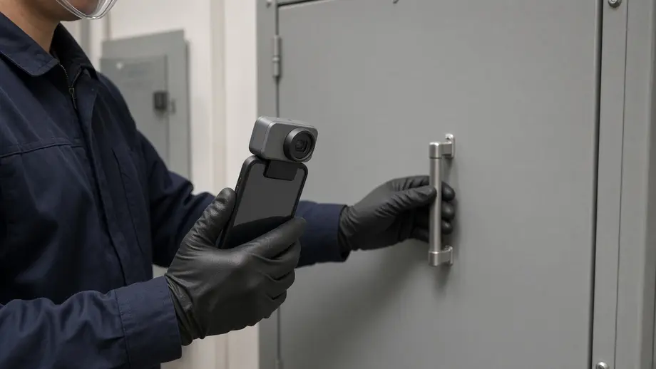
The hard part of a budget camera is getting enough detail without paying for a pro handheld. The TC001 Max phone thermal camera, sold through Olight's OSelect line, answers with a 256 × 192 sensor, <40 mK sensitivity and a 25 Hz frame rate. Olight's page says it needs "no batteries, charging, or wireless pairing" and "works without removing most phone cases." Its Dual Fusion mode blends the thermal image with a visible-light camera, which helps you tell which breaker you are looking at. Its measurement tools include center, hot and cold spots, plus user-set dots, lines and rectangles for side-by-side phase comparison.
The limits are real. The wide 56° lens means small targets need you close. The TC001 Max user manual shows an emissivity value and a "Distance to Spot" entry in the app's Temperature Correction screen, but neither the manual nor the product page lists a reflected temperature correction, so treat bare-metal numbers as comparisons, not measurements. The manual also tells you to avoid "measuring in direct strong light or near reflective surfaces," which describes most open panels. It is rated IP54 and for a 1 m (3.28 ft) drop, and it works from 14 °F to 122 °F. It also depends on your phone, which has to be in your hand at the panel. It lists at $309.00 (regular price, September 2026). If you sign off on annual NFPA 70B surveys, buy a handheld like the E8 Pro and keep the TC001 Max as a service-van finder.
FLIR E8 Pro: Best for Documented Surveys
Survey work needs repeatable numbers from a safe distance. The FLIR E8 Pro's 320 × 240 sensor and 33° lens give it the finest IFOV in this comparison. FLIR lists a Delta T tool as "NFPA 70B compliant," emissivity presets with a custom value, and reflected temperature correction. The trade-off is price, at $3,299.00, and weight, at 1.34 lbs. For a contractor who bills for infrared surveys, that math can work. For one hot-spot hunt a month, it rarely does.
FLIR Edge Pro and FLIR C5: The Middle Options
The Edge Pro connects to the phone over Wi-Fi, and FLIR lists remote operation "up to 5 m (16.4 ft) from smart device." That lets the phone stay out of the enclosure opening. The C5 is a standalone pocket camera with a touchscreen and 5 MP visual camera. Both use a 160 × 120 sensor, so they need a closer stance than the TC001 Max to put 3 × 3 pixels on the same lug.
Why Do Bare Copper, Galvanized Steel and Plastic Read Differently?
Bare copper, galvanized steel and plastic read differently because they emit infrared energy at very different rates, a property called emissivity. Polished copper can be as low as 0.02 to 0.03, so the camera sees mostly reflections. Electrical tape and painted surfaces sit near 0.90 to 0.95 and read close to their true temperature.
Emissivity runs from 0 to 1. A low-emissivity surface acts like a mirror, so the camera reads the heat of whatever it reflects, including you. The ISA guide notes that "aluminum bus, however, is very reflective, and so are copper and some kinds of stainless steel," while "ceramic, rubber, and most electrical tape and conductor insulation have relatively high emissivities as well."
This table pulls values for common panel surfaces from Appendix E and Appendix F of Reclamation's FIST 4-13 manual and from the ISA guide.
| Surface you see in a panel | Emissivity (source) | What it means for your reading |
|---|---|---|
| Highly polished copper | 0.02 (FIST, 100 °F) | Almost pure reflection; the number is meaningless |
| Polished copper | 0.03 (FIST) | Same problem |
| Matte copper | 0.22 (FIST) | Still reads far too low when hot |
| Rolled copper | 0.64 (FIST) | Better, still needs correction |
| Black oxidized copper | 0.78 (FIST) | Usable with the correct setting |
| Bright galvanized zinc | 0.23 (FIST) | Reflective; common on enclosures and brackets |
| Black electrical tape (3M Scotch 33) | 0.95 (FIST) | Reference surface many thermographers use |
| Flat paint | About 0.90 (FIST) | Reads close to true temperature |
| Painted surfaces in general | 0.90 to 0.98 (ISA guide) | Good targets |
Four habits keep reflections from fooling you:
- Aim at the cavity. Reclamation's manual notes that the spot "where a lug or nut meets the connection surface will form a small cavity" with higher emissivity. Put your spot meter there, not on the flat face of the lug.
- Move and watch. If a hot spot slides across the part as you step sideways, it is a reflection. A real hot spot stays put.
- Read the insulation next to the lug. The first inch of conductor insulation often gives a steadier comparison than the bare metal.
- Compare like with like. Three identical lugs on three phases share the same emissivity, so their difference is real even if each absolute number is off.
Warning: The tape method only works if the tape goes on before the equipment is energized. Reclamation's manual says the technique "requires the tape to be placed on the target material prior to energizing, loading, or heating the equipment to be monitored." Never reach into a live enclosure to apply tape. Add tape targets during a planned outage.
How Hot Is Too Hot? NETA Temperature Rise Criteria
NETA's criteria call for immediate repair when a component runs more than 15 °C (27 °F) hotter than a similar component under similar load, or more than 40 °C (72 °F) above ambient. Smaller differences call for monitoring or repair at the next opportunity. Fluke's guide gives the same two immediate-action thresholds, citing NETA.
Reclamation's FIST 4-13 reproduces the severity table from NETA's Maintenance Testing Specifications (2005 edition). This table restates it in both units. "Over similar" means compared with the same part on another phase under similar load.
| Difference over similar component | Difference over ambient | NETA implication (as quoted by Reclamation) |
|---|---|---|
| 1 to 3 °C (2 to 5 °F) | 1 to 10 °C (2 to 18 °F) | Possible deficiency: monitor and repair when possible |
| 4 to 15 °C (7 to 27 °F) | 11 to 20 °C (20 to 36 °F) | Probable deficiency: investigate further and repair when possible |
| Not listed | 21 to 40 °C (38 to 72 °F) | Deficiency: repair at next opportunity |
| More than 15 °C (more than 27 °F) | More than 40 °C (more than 72 °F) | Major deficiency: repair immediately |
Load changes everything. Heat at a bad connection comes from current squared times resistance, so a joint at 40 percent load makes only 0.4 × 0.4 = 16 percent of the heat it would make at full load. Reclamation's manual prints published load correction factors "adapted from" a 2002 study and says they should be "used cautiously," since there are "no simple load correction factors."
This table shows those factors and what they do to a modest reading.
| Load when scanned | Multiplication factor (FIST 4-13) | A 5 °C rise over similar would be about | NETA category at that estimate |
|---|---|---|---|
| 100% | 1 | 5 °C | Probable deficiency |
| 80% | 1.4 | 7 °C | Probable deficiency |
| 60% | 2.2 | 11 °C | Probable deficiency |
| 50% | 3 | 15 °C | Top of probable deficiency |
| 40% | 4.3 | 21.5 °C | Major deficiency |
The lesson: a small difference at light load can hide a serious problem. Record the load with every image, and rescan at a higher load before you downgrade a finding.
The Three-Phase Comparison Method, Step by Step
The three-phase comparison method means imaging matching parts on all three phases in one frame, under steady load, and judging the difference between them rather than any single temperature. It works because the three parts share material, emissivity, airflow and load. That cancels most of the errors that make absolute readings unreliable.
Reclamation's manual says the comparison object "must be subjected to the same conditions as the target object," and lists the same manufacturer, load, emissivity and environmental conditions as examples. Here is the sequence a qualified person can follow once the employer has approved the task.
- Confirm load. The ISA's thermal imaging electrical maintenance guide states: "The electrical equipment being inspected must be at or above 40 percent of nominal load to detect problems with a thermal imager." Reclamation adds that "at least 45 minutes should expire after a load change."
- Measure load per phase with a clamp meter and write it down.
- Set the camera: emissivity for the surface, reflected temperature, and distance.
- Frame all three phases together at a fixed, marked distance, as square to the surface as possible.
- Lock the span so the same colors mean the same temperatures on every image.
- Capture and step back. Reclamation recommends a "Freeze and Leave" practice: capture the image and leave the area immediately.
- Read the delta later, away from the equipment, and assign a NETA category.
- Rescan after repair under similar load to prove the fix.
Every image should carry enough data that someone else can repeat it. This report template lists the fields Reclamation's manual says to record, arranged for one finding per row.
| Field | Example entry |
|---|---|
| Equipment and location | Panel LP-2A, Room 114, main lugs |
| Date, time and inspector | Name and qualification level |
| Camera make, model and emissivity used | Model, emissivity 0.95 on insulation |
| Distance to target | 1.2 m (4 ft), floor mark |
| Load per phase at time of scan | A 142 A, B 138 A, C 147 A |
| Ambient temperature and air movement | 24 °C, HVAC supply nearby |
| Hot spot, reference and delta | Phase C lug 61 °C vs phase A 44 °C = 17 °C over similar |
| NETA category and action | Major deficiency: de-energize and repair immediately |
| Images attached | Thermal and visible, before and after repair |
The example numbers are for illustration only. They show how the fields fit together, not a real finding.
Common Mistake: Scanning a Panel With No Load
The most common mistake is scanning a panel when little or no current is flowing, such as at night or on a weekend. A loose lug only heats when current crosses it. With no load, a failing joint can look exactly like a good one, and the scan gives you false confidence instead of a finding.
The FIST manual says "it is critical that electrical equipment be examined at full load," and that light loads "may not adequately heat a problem area." Airflow compounds the problem. Reclamation reports that even indoors, "ventilation fans, air conditioning, and even natural ventilation can reduce the apparent temperature."
This list pairs other frequent mistakes with a fix.
- Trusting the color palette. Auto-range makes a 2 °C spread look dramatic. Fix: lock the span and read numbers.
- Measuring bare copper as if it were paint. Fix: aim at cavities and insulation, and compare phases.
- Standing too far back with a wide lens. Fix: use the IFOV table above, or move to a camera with more pixels.
- Mistaking a warm cover for the problem. Fix: plan an inspection of the internal parts with the equipment de-energized.
- Skipping the rescan. Fix: image the same point, same distance, similar load after repair.
- Scanning right after opening a cover. Reclamation notes that "the simple act of opening an enclosure door or removing a protective covering can quickly change the temperature of a component." Fix: scan promptly and record how long the cover has been open.
Is It Safe to Scan an Open Electrical Panel Under NFPA 70E?
Scanning an open, energized panel is safe only when a qualified person does it under the employer's electrical safety program, with a justified reason, the right PPE and the NFPA 70E steps followed. Removing the cover is itself a separate hazardous task that needs an energized electrical work permit. If you are not a qualified electrician, keep the cover on.
Federal rules start from de-energizing. OSHA 29 CFR 1910.333 states: "Live parts to which an employee may be exposed shall be deenergized before the employee works on or near them, unless the employer can demonstrate that deenergizing introduces additional or increased hazards or is infeasible due to equipment design or operational limitations." Thermography is one of the few tasks that needs energized equipment, because the load is the point. The same regulation says "only qualified persons may work on electric circuit parts or equipment that have not been deenergized."
NFPA's Coache is direct about the cover. In the post linked above, he writes: "Opening the enclosure requires an EEWP." He adds that visual inspection of justified energized parts "is exempt from an EEWP only if the restricted approach boundary is not crossed, proper safe work practices are followed, and proper personal protective equipment (PPE) is used." He also notes that any opinion in the post is his own, not NFPA's official position.
PPE depends on the incident energy study for that equipment. The ISA guide lists what the job may include, "depending on the situation and the incident energy level": flame-resistant clothing, leather-over-rubber gloves, leather work boots, and an arc-flash-rated face shield, hard hat and hearing protection or a full flash suit.
This table turns those rules into a pre-scan checklist.
| Rule (source) | What you do before the camera comes out |
|---|---|
| De-energize unless justified (OSHA 1910.333(a)(1)) | Write down why the scan must be done under load |
| Qualified persons only (OSHA 1910.333(c)(2)) | Confirm the person is qualified for this equipment and task |
| Opening the enclosure needs an EEWP (NFPA blog, Coache) | Treat cover removal as its own permitted task |
| Stay outside the restricted approach boundary (NFPA blog) | Mark the boundary and plan the camera distance from it |
| PPE per incident energy (ISA guide) | Check the arc-flash label and wear the listed PPE |
| No conductive apparel near exposed parts (OSHA 1910.333(a)(8)) | Remove rings, watch bands and metal headgear, or insulate them |
| Illumination required (OSHA 1910.333(c)(4)) | Light the space before entering; never reach in blind |
| Freeze and Leave (FIST 4-13) | Capture the image, then step away before reviewing it |
Safety note: Follow NFPA 70E, your employer's electrical safety program and your state and local rules. Reclamation's manual adds that when the camera has your full attention you may miss other hazards, and it recommends working with an assistant. A thermal camera never replaces a voltage test before you touch anything.
Where panels are scanned every year, infrared windows or viewing ports are worth a look. Reclamation recommends them "so that IR inspections and visual inspections can take place without removing the panels," and notes that glass covers and some plastics are not transparent to infrared.
What Light Should You Use While Scanning a Panel?
Use a hands-free light on a medium setting while you scan a panel, so you can read breaker labels, the panel schedule and the visible-light photo without holding anything. OSHA requires light that lets you work safely near exposed energized parts. The thermal image needs no light at all, but your report does.
OSHA 1910.333(c)(4) says employees "may not enter spaces containing exposed energized parts, unless illumination is provided that enables the employees to perform the work safely," and that "employees may not reach blindly into areas which may contain energized parts." A basement electrical room or a utility closet often has one ceiling fixture behind you, which throws your shadow onto the panel.
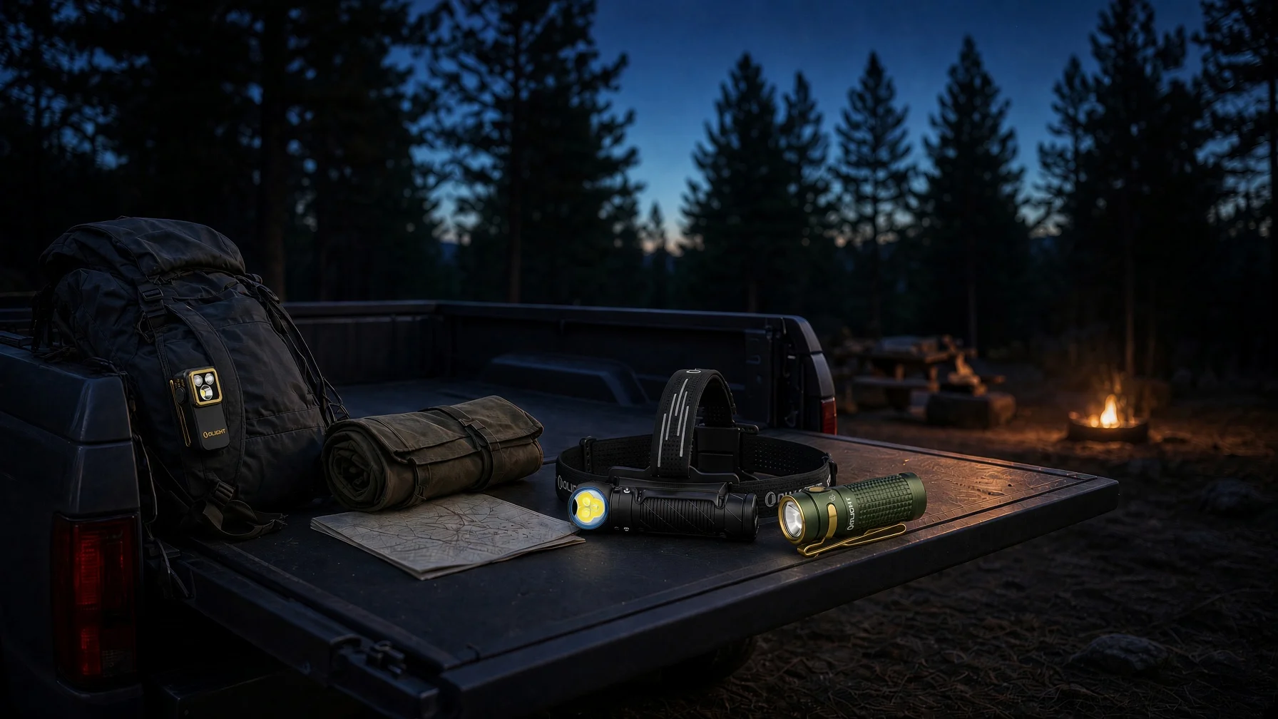
The Olight Perun 3 Mini headlamp fits this job because it keeps both hands free for the camera and the clamp meter. Olight lists 1,250 lumens and 6,000 candela on Turbo for the cool white version. For panel work, Med at 100 lumens is the practical setting. At 4.5 hours on Med, it covers a 20-panel survey at about 10 minutes per panel (200 minutes, or 3.3 hours) on one charge. Low at 10 lumens runs 30 hours for reading the directory up close. The quick-release bracket turns it into a handheld, and the magnetic tailcap lets you stick it to a steel surface to light a wall of switchgear.
Be clear about the limits. The Perun 3 Mini body is aluminum alloy, and Olight does not rate it as nonconductive or arc rated. Treat it like any metal item under OSHA's conductive apparel rule: keep it on your head outside the opening, and never put it inside an energized enclosure. Turbo at 6,000 candela works out to about 6,000 lux at 1 m, which washes out labels and bounces off glossy breaker faces, so stay on Med or Low. It lists at $64.99 (regular price, September 2026). At that time the Orange CW color and two Premium editions showed as sold out, so check stock for the color you want. For more hands-free options, see Olight's guide to the best rechargeable headlamp for different job types.
Who Makes the Best Thermal Imaging Camera?
No single maker is best for every electrician. FLIR and Fluke are the established professional brands, with the widest lines of handhelds and reporting software. TOPDON, whose TC001 Max Olight sells, focuses on phone-based cameras at lower prices. Pick by native resolution, lens, emissivity controls and reporting, not by the logo.
The spec comparison above shows why brand is a weak filter. Within FLIR's own range, the C5 and the E8 Pro differ by 4 times the pixel count and nearly 5 times the price. The TC001 Max, from a phone-camera maker, lists the same <40 mK sensitivity as the E8 Pro. Fluke's thermal camera range spans pocket imagers to high-resolution models as well.
This decision framework narrows the choice by how you work.
| How you work | What to prioritize | Camera class |
|---|---|---|
| Service calls, a few hot-spot checks a month | Price, speed, a visible photo | Phone plug-in such as the TC001 Max |
| Residential and light commercial troubleshooting | Standalone use, drop rating, cloud upload | Pocket camera such as the FLIR C5 |
| Keeping the phone out of the enclosure opening | Wireless link between camera and screen | FLIR Edge Pro |
| Annual NFPA 70B surveys with signed reports | Resolution, narrow lens, emissivity and reflected temperature correction, delta-T tool | 320 × 240 or higher handheld such as the FLIR E8 Pro |
If your work also takes you to rooftop units and line sets, the HVAC guide to the best thermal imaging camera for HVAC compares the same cameras for coils and refrigerant lines. For motors, belts and brakes, see the guide to the best thermal imaging camera for mechanics.
Can a Thermal Camera See Wires in Walls?
No. A thermal camera cannot see through drywall; it only reads the surface temperature of the wall. A wire shows up only when current warms it enough to change the surface temperature, which rarely happens with normal loads in insulated walls. To locate wiring, use a cable tracer or a non-contact voltage tester instead.
FLIR's answer to can thermal imaging see through walls is plain: "No, thermal cameras cannot see through walls, at least not like in the movies." The same article explains that if something inside the wall "causes enough of a temperature difference, a thermal imager will be able to sense it on the surface of the wall." FLIR's electrical contractor article recommends a cable locator, which can "locate and trace powered or unpowered wires and cables in walls, ceilings, floors, and underground."
The TC001 Max user manual draws the same line for its own sensor: the device "is designed to measure surface temperatures but cannot detect heat through transparent materials like glass, acrylic, or water, nor through opaque objects." That glass limit is also why you can't scan a panel through a plain window or a clear plastic cover.
Where a thermal camera does help with walls is heat that should not be there. A warm patch around a receptacle or switch plate can point to a loose device terminal or an overloaded circuit. Treat that as a reason to de-energize the circuit and open the box, not as a diagnosis.
How These Cameras Were Compared
The cameras in this guide were compared on published specifications and standards, not on bench measurements. Every number comes from the maker's product page or from the cited standard or manual. The IFOV, spot size, load and runtime figures are calculations from those numbers, and the formula for each one is shown next to the result.
This table explains each comparison criterion and where its data comes from.
| Criterion | Data source | Method | Why it matters to electricians |
|---|---|---|---|
| Smallest measurable target | Native resolution and FOV from each maker | IFOV × distance × 3 (FLIR 3 × 3 rule) | Decides whether you can read one lug from outside the boundary |
| Sensitivity and accuracy | Maker spec sheets | Compared as listed | Small deltas matter in NETA categories |
| Emissivity controls | Maker spec sheets | Listed or not listed | Bare metal readings depend on it |
| Durability | IP and drop ratings from makers | Compared as listed | Panels live in dusty rooms and on ladders |
| Severity thresholds | NETA table via FIST 4-13; Fluke | Restated in °C and °F | Turns a delta into an action |
| Load effect | FIST 4-13 load correction table | Worked example with a 5 °C reading | Shows why light-load scans mislead |
| Safety requirements | OSHA 1910.333, NFPA blog, ISA, FIST 4-13 | Quoted and turned into a checklist | Keeps the scan inside the rules |
| Price | Maker product pages, September 2026 | Regular price as listed | Budget fit |
Before you pick the best thermal imaging camera for electricians on your crew, run through this action list:
- Write down the smallest target you need to read and the distance you are allowed to stand.
- Use the IFOV table to pick a resolution and lens that meet the 3 × 3 rule at that distance.
- Confirm the camera lets you set emissivity and reflected temperature if you need numbers.
- Set up a report template with load, distance and emissivity fields.
- Schedule scans at 40 percent load or more, and 45 minutes after any load change.
- Get the task written into your employer's electrical safety program before the first open-panel scan.
FAQ
Changelog
- September 21, 2026: First published. Olight and FLIR specs and prices checked September 24, 2026.